Key Benefits
- Reduced shutdown time
- Increased safety
- Automated level control
- Modular design
Flotation Bypass System
Flotation Bypass System is a custom designed system that provides a means of bypassing an individual cell in the flotation cell bank, without the need to shut down the entire line for extended periods of time.
What we offer
A simple means to minimise downtime
With only a minor modification to your flotation circuit, you can eliminate thousands of hours of unnecessary downtime throughout the year. The ability to maintain high levels of production in this portion of the circuit is one of the most economically strategic steps you can take in your plant.
The bypass system is an uncomplicated operation that works on the same proven principle as a typical gravity-based dart valve system. It does not need to be connected to the plant’s main control system. Tailored to the specific needs of your site, installation is straightforward and can be completed in 24 hours.
Key Benefits
Reduced shutdown time
Significantly reduces downtime associated with scheduled maintenance
Safety
Allows maintenance work on isolated cells without the risk of slurry over flowing the cell
Automated level control
Standalone Multi-Sense® level sensor, installed into the upstream cell, signals the pinch valve in the bypass line to control the valve position
Modular design
Modular design allows the system to be moved up or down the flotation bank to bypass all but the first cell
Features
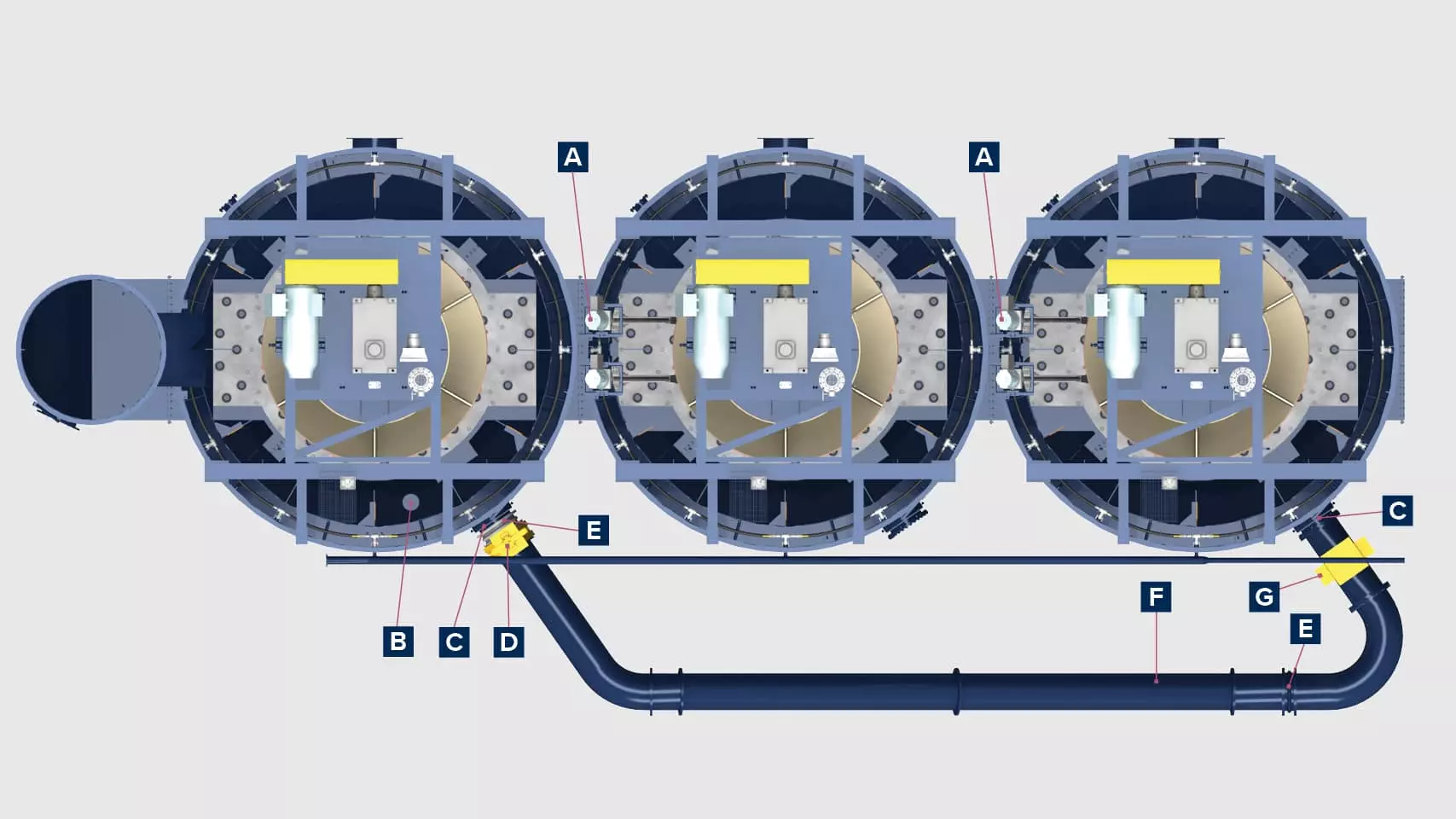
A - Upstream / downstream isolation flange
The bypassed cell is safely isolated from the others by installing an isolation flange on the upstream and downstream dart valve openings.
B - Multi-Sense® level sensor
Inserted into the upstream cell, the sensor relays a signal to the pinch valve in the bypass line, regulating its position based on operator input of the manual level setpoint in the control panel.
C - Modified manway hatch
The manway hatch cover is modified to allow connection of the bypass pipe to the upstream and downstream cells.
D - Knife gate valve
A knife gate valve is located on the upstream end of the bypass line to aid in isolating the system, if necessary.
E - Flexible expansion joints
Expansion joints in the piping system accommodate variations in distance between the cells as the system is moved up or down the bank.
F - Piping segments
HDPE pipe segments are custom-sized for your circuit to accommodate your site’s flow rate and floor plan.
G - Pinch valve
Located on the downstream end of the bypass line, the pinch valve is connected to and regulated by the Multi-Sense® level sensor, which is inserted into the upstream cell
Downloads
Brochure
Keep exploring