Key Benefits
- High reliability
- Optimal fuel and power consumption
- Unmatched fuel flexibility
- Effective emission control
Cyclone Preheaters: Better throughput; less spend
Heating raw material to calcination temperatures has traditionally demanded a complex, high-energy, fuel-intensive process. Our Cyclone Preheaters change all of that. Their unique design simplifies calcination, while also allowing for better emission control and fuel efficiency, for a cost-effective solution that’s also easy to use.
What we offer
Optimise your preheating processes, with innovative Cyclone Preheaters
Today’s modern plant preheats raw meal to calcination temperature in a multi-stage cyclone preheater. Most of the calcination process takes place in a separately fired, stationary calciner, while the remaining calcination and clinkerization process takes place in a rotary kiln.
FLSmidth has precisely what producers need to make it an optimal process. With its low emissions, flexibility and ease of operation, the FLSmidth In-Line Calciner (ILC) preheater has been a success since its debut in 1976. And thanks to our continual development of the system ever since, the ILC is still at the forefront of technology. Flexible enough to meet future demands as well, the ILC can help plants stay in the lead for many years to come.
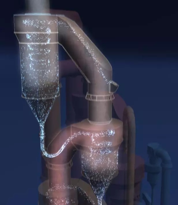
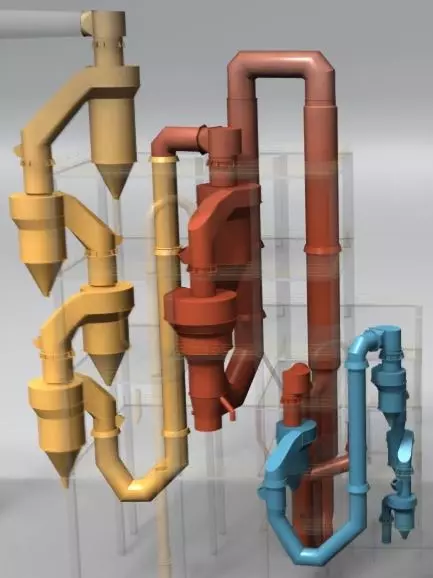
How the ILC preheater works
Raw meal is introduced at the inlet gas duct to the Stage I (top) cyclones. It is subsequently preheated by hot, countercurrent gas flow as it is continuously collected and passed down the other cyclone stages in the preheater to the calciner. Fuel is burned in the calciner to achieve 92-95% of the total material calcination before collection in the bottom cyclone and entrance into the kiln. Combustion air for the calciner is taken from the kiln via the riser duct and through a separate tertiary air duct from the cooler.
Proven NOx reduction from high temperature “stage-less” combustion is incorporated into the standard design of the ILC preheater. It’s a very uncomplicated and effective way to create low NOx emissions with only one firing location, one meal split and one tertiary air stream entering tangentially to the calciner.
Our design is based on dividing the meal from the second-lowest stage cyclone to the kiln riser and the calciner. These feed points are separated by an expanded riser duct that forms a NOx reducing zone. That is, the calcining chamber is built (at least partially) into the kiln riser. All of the calciner fuel is introduced to the kiln riser duct with less oxygen than required for complete combustion, thereby forming a reducing atmosphere.
Above the reduction zone is the main calciner vessel, which is divided into two or more sections separated by a notch. The changes in cross-sectional areas create turbulence that ensures effective mixing of fuel, raw meal and gas, improving heat transfer and combustion. The calciner outlet loop duct ensures optimum gas retention time, further mixing and complete fuel combustion.
Optionally, the second- or third-lowest stage cyclone material can be further split to allow for diversion of a portion of the meal directly into the upper section of the calciner. This creates a “hot zone” in the lower section of the calciner that is conducive to burning difficult fuels and further NOx reduction.
Burn coarse alternative fuels
Increasingly, plants are burning solid waste fuels to achieve a variety of benefits. By integrating the ILC with our HOTDISC combustion device, it is possible to achieve unsurpassed fuel flexibility with minimal impact on process stability and performance.
The HOTDISC is a safe, simple and effective combustion device that has proven to be the best available technology for substituting calciner fuel with coarse alternative fuels. With the HOTDISC, plants can burn all kinds of solid waste in sizes up to 1.2 metres. This eliminates the need for expensive shredding of lumpy waste material. Read more about HOTDISC →
An optimal solution
Preheater and calciner design has a strong influence on operational efficiency, emissions and ability to effectively burn different types of fuels. Every FLSmidth preheater calciner system is optimised for the individual situation in which it is to be used. FLSmidth’s decades of experience in this area enables us to deliver solutions that are ideal for each plant’s specific challenges.
Key factors that go into designing an optimal solution:
- Number of stages/cyclones
FLSmidth’s preheater calciner systems are equipped with up to six stages of cyclones. The number of stages is normally determined by the drying requirements in the different grinding systems. Emission requirements or other use of the preheater exit gas can also affect the number of stages, as can practical matters such as local building codes/height restrictions. - Number of strings
The number of strings of cyclones is generally related to the plant’s capacity requirements – the more capacity needed, the more strings typically needed. Most commonly, the system encompasses one or two strings, but more may be considered for the largest of plants. A transition from one to two strings relates to the size of the cyclones and the resulting volume of the preheater construction. - Size of cyclones
The selection of cyclone sizes is a balance of having the smallest cyclone dimensions while maintaining the lowest overall pressure drop through the preheater. This is to minimise the induced draft (ID) fan power consumption – the most power consuming part of a kiln system.
The size of cyclones relates to the maintaining of desired gas velocity criteria and efficiency.
Increasing the preheater cyclone dimensions reduces the pressure drop. But for any given cyclone geometry, stable preheater operation (without raw meal falling through the riser ducts) requires a certain minimum gas velocity.
Key benefits
Cyclone Preheaters — reliability, efficiency and ease of operation
- High reliability
- For you to get the most out of your preheaters, they have to be able to withstand continual use and extreme stress. Our Cyclone Preheaters are made from durable materials, and constructed to outlast other preheater solutions on the market. This means less repair and maintenance downtime, improved throughput and better returns for your business.
- Optimal fuel and power consumption
- High energy costs have a way of eating into your profits. By optimising both fuel and energy consumption, our Cyclone Preheaters empower your business to spend less, and net more.
- Unmatched fuel flexibility
- Reduce operational expenses by relying on course, alternative fuels. Integrate our Cyclone Preheater with our safe, simple HOTDISC combustion device for cost-saving fuel flexibility.
- Effective emission control
- Reduce your operation’s negative environmental impact; our Cyclone Preheaters offer an effective solution, with low NOx emissions with only one firing location, one meal split and one tertiary air stream entering the calciner.
Product features
Advanced preheater technology to match your business
Design characteristics
- Full capacity range of today’s plants of 13,000 tpd or more
- Built with single or multiple preheater strings with up to 6 cyclone stages
- Ratio of firing in calciner: 55-65%
- Calcination at kiln inlet: 92-95%
- Allowable bypass of kiln gas: 0-60%
- For bypass of kiln gas up to 100%, special ILC version applies
- Optional “hot zone” in lower section of calciner
- Available with or without the HOTDISC™ combustion device reactor for burning coarse alternative fuels
Operating characteristics
- High-efficiency cyclones with low pressure drop resulting in low fuel and power consumption
- Lowest NOx emission from unique high-temperature reduction zone
- Simultaneous low CO emission especially due to calciner notch and outlet loop duct
- Uncomplicated operation with single entry locations of calciner fuel and tertiary air
- Suitable for firing both traditional and alternative fuels
Cyclone preheater components
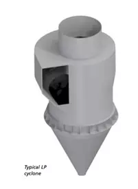
- Cyclones
-
FLSmidth preheaters have been based on proven low pressure loss (LP) cyclones. The unique design of the LP cyclone ensures high thermal efficiency and low pressure drop while enabling a flexible and space-saving layout. LP cyclones have no horizontal surfaces on the inside for material to accumulate, thereby securing stable operation. The top stage has a special geometry to provide the lowest dust loss while maintaining low pressure drop. LP cyclones are not just for completely new preheaters but may be individually fitted to upgrade existing preheaters.
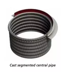
- Central pipes
-
Central pipes (thimbles) are standard in all cyclone stages to provide high separation efficiency. The lowermost cyclones feature a cast, segmented design with a hanging suspension system and common elements throughout. This enables easy installation and maintenance.
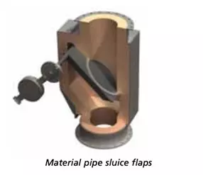
- Sluice flaps and distribution boxes
-
To prevent gas from bypassing up through the material pipes between the cyclone stages, the pipes are equipped with sluice flaps (tipping valves) designed for full opening. Good meal distribution in the cyclone riser ducts is ensured by adjustable spreader plates in the distribution boxes.
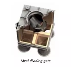
- Dividing gates
-
Robust dividing gates are used to precisely and consistently distribute meal to the different sections of the riser duct and calciner. One gate is capable of dividing meal into two, three, or four different streams.
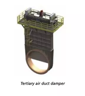
- Tertiary air duct damper
-
To balance the combustion air flow between the kiln and calciner, a tertiary air duct damper is provided for reliable regulation of the tertiary air gases. The damper design features a solid refractory blade for long, reliable life.
Keep exploring